

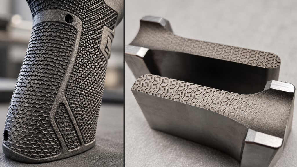
A texture reference can show the intended appearance of a surface. It may leave a critical design decision unresolved: where should that texture change, and what should the transition look like?
For engineers and tooling teams, the boundary between two surface treatments deserves its own specification. A textured panel meeting a smooth border, a pattern wrapping around a curved face, and a gradual fade each communicate a different intent.
St. Paul Engraving works with customers to review surface requirements and evaluate a proposed laser texturing approach. A productive discussion starts with the intended result, the actual geometry, and a shared reference for review.
The firearm application examples featured here show two distinct faded texture treatments: a grip with a blended backstrap and another component from the same firearm with a faded aggressive texture. An accompanying video demonstrates how the texture meets across two separate parts when they are brought together. Each example highlights a different question to resolve before production.
Example 1: A blended backstrap
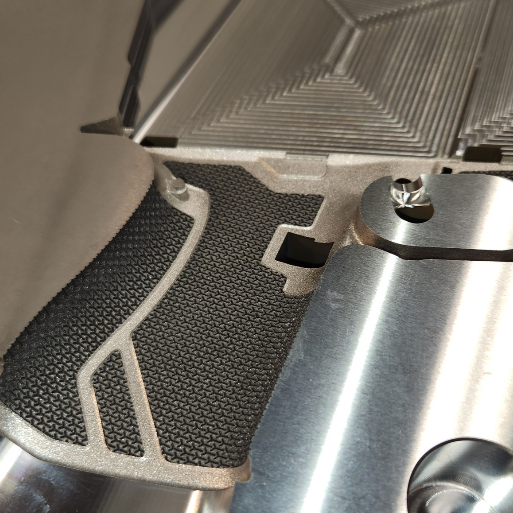
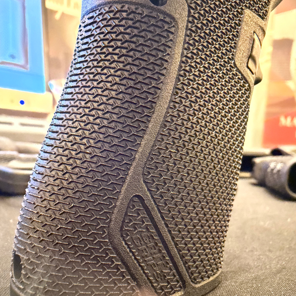
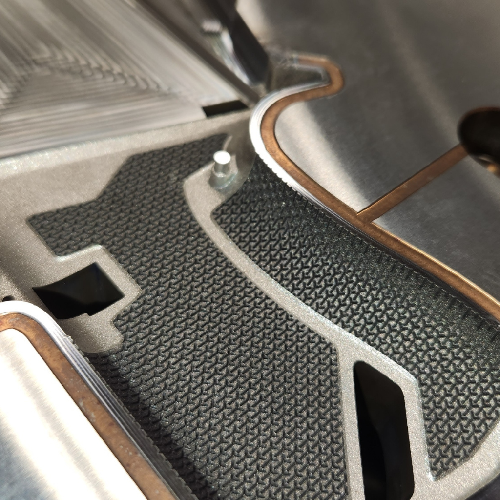
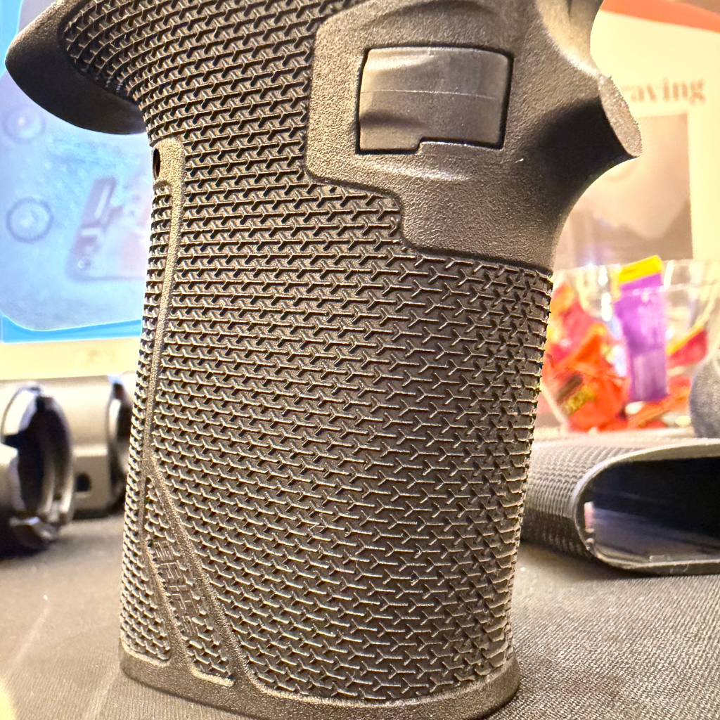
On the firearm grip, the backstrap features a blended, faded texture transition. The relevant design decision extends beyond choosing the pattern: the fade itself is part of the intended surface.
For a project with this type of transition, identify where the full pattern should begin to change, where the fade should finish, and how it should relate to the surrounding textured areas. Include views that show the transition around the curved surface, rather than relying on a single flat view.
An approved reference helps SPE and the customer discuss the intended character of the blend. If tactile characteristics are part of the requirement, include them in the review criteria alongside appearance.
Example 2: A faded aggressive texture on another component
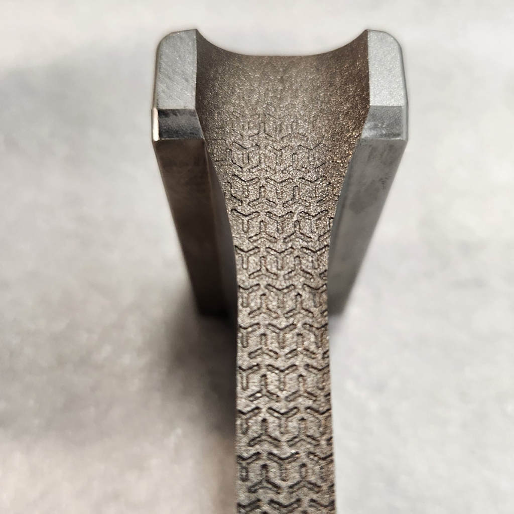
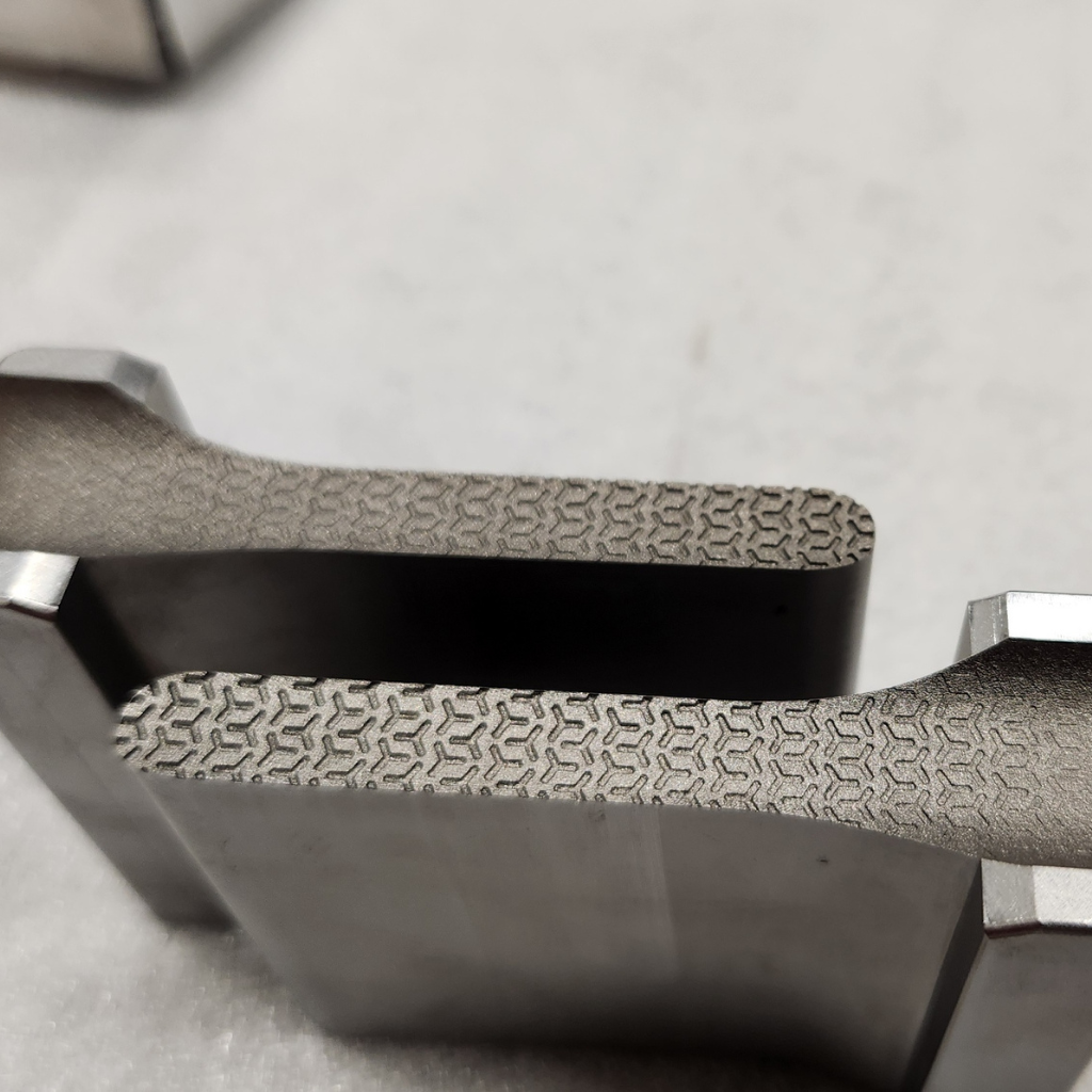
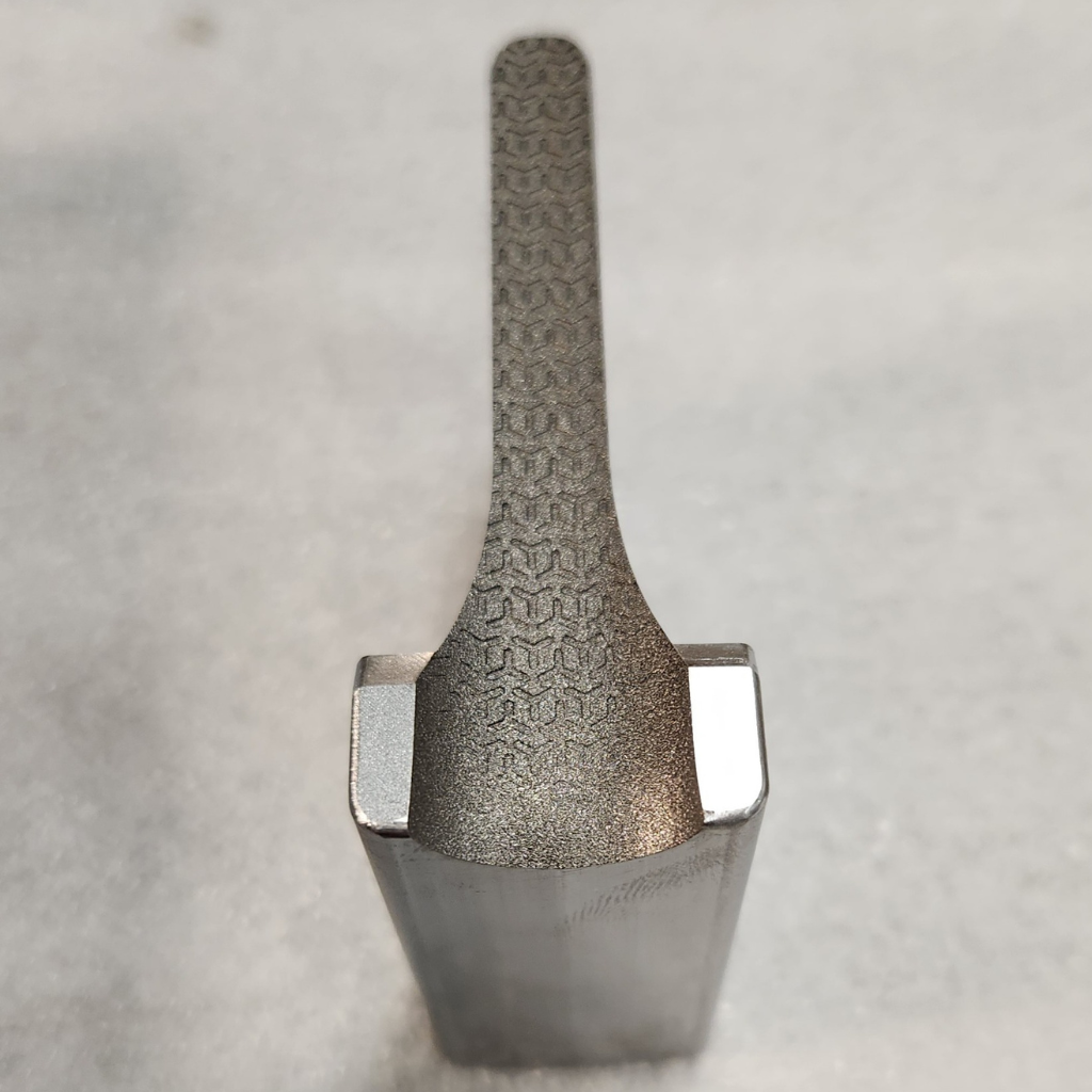
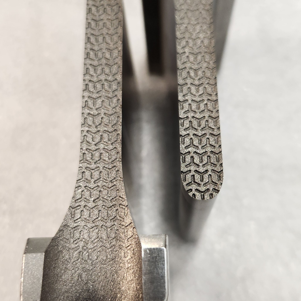
A second component from the same firearm uses another faded aggressive texture treatment. This example brings the fade into focus on a different geometry.
Using the same general texture concept across a product does not fully define the treatment of each component. The fade location, direction, extent, and relationship to nearby features still need to be specified for that surface.
Review each component individually, then review how the surfaces relate within the product. Identify which characteristics should remain shared and which transitions are specific to the component.
Texture alignment across separate parts
The accompanying video shows two textured parts separated and then brought back together, demonstrating the visual continuity of the pattern at the joint.
This introduces an additional requirement: how should the texture meet when the parts are together?
For a project requiring this type of alignment, provide the assembled geometry as well as the individual part models. Identify the joint, the intended pattern direction, and the relationship between the texture features on either side. Define what will be reviewed in the assembled condition.
Here, “seamless” describes the visual matchup of the texture. The parts remain separate, and their physical joint still exists. Agreeing on that distinction makes the acceptance criteria more precise.
A video can make this relationship easier to understand than an isolated close-up. Reviewing both the separated and joined conditions shows which surfaces belong to each part and how the pattern relates across the interface.
Start with the surface intent
Before selecting a texture, define what the surface is intended to accomplish.
Is the requirement primarily visual? Does it involve a particular tactile character? Is the team matching an existing component or introducing a new pattern? If a functional benefit is intended, identify how that benefit will be evaluated.
Separate the desired appearance from any performance requirement. A photograph can communicate design intent, but it cannot establish how a finished part will perform.
Describe the transition as clearly as the adjoining surfaces. “Fade here” leaves room for interpretation. A more useful request identifies the start and end regions, the direction of the fade, and the reference that defines its appearance.
Locate the transition on the geometry
Mark the treatment areas on the drawing or CAD model. Identify where each texture begins and ends, as well as any areas that must remain untreated.
Useful questions include:
- Does the boundary follow an edge, feature, or defined line?
- Should the texture stop before a radius or continue across it?
- Is the change abrupt or gradual?
- How should the pattern behave around corners?
- Which adjoining surfaces will be visible together on the finished product?
For example, a request for a textured panel surrounded by a smooth border should identify both the pattern and the border limits. If the panel curves into a sidewall, the model should show whether the texture continues onto that wall.
This is a planning example, not a specification for every mold. The appropriate boundary depends on the project’s design intent and geometry.
Review access and part orientation
A boundary that looks straightforward in one drawing view may be harder to interpret on a recessed or curved surface.
Include the surrounding geometry in the review. Surface direction, adjacent features, and the proposed setup all belong in the discussion of how the required areas will be accessed.
SPE’s 5-axis laser capability brings part orientation into that evaluation. Suitability still needs to be assessed for the actual tool and surface requirements.
Share the CAD model where available, along with annotated views that make the intended treatment areas clear. Identify any setup restrictions or features that must be protected.
Provide material and manufacturing context
The project information should distinguish between the tool being treated and the part it will produce.
Provide the tool material, its current surface condition, and any known coatings, repairs, or previous treatments. Include the intended molding material and relevant manufacturing requirements for SPE to consider with your team.
If the proposed transition crosses a repaired area or an existing texture, flag that location early. It is a detail to review before agreeing on the approach.
If release, material flow, or another production concern informs the texture choice, describe the requirement and the planned evaluation. Keep those expectations explicit rather than assuming the pattern alone establishes the outcome.
Choose a reference everyone can use
Agree on which reference defines the intended result: an approved physical sample, texture file, drawing revision, or combination of these.
A reference image can communicate the overall look while leaving scale, coverage, and tactile expectations unresolved. Record what each reference is intended to define.
For a transition, clarify:
- The texture on each side of the boundary
- Pattern scale and direction
- The extent of any fade region
- The relationship to adjacent untreated surfaces
- The revision that applies to the project
When matching an existing surface, identify the specific area that serves as the reference. If several samples differ, choose the governing sample before work begins.
Agree on review expectations
Define how the surface and its transition will be reviewed before production work begins.
Who will approve the result? What sample, image, or measurement will be used? Which criteria are visual, and which require another form of evaluation?
For visual review, agree on the viewing conditions and reference. If measured criteria are required, identify them with SPE rather than relying on terms such as “consistent” or “close match.”
Also establish how changes will be documented. A revised boundary or texture file should be tied to the applicable drawing, tool, or cavity so the team can identify which version governs the work.
Prepare for a focused project discussion
A useful starting package includes:
- A drawing or CAD model with treatment areas marked
- Tool material and current surface condition
- Intended molding material and manufacturing context
- Approved texture references
- Transition locations and untreated areas
- Review criteria, revision information, and project timing
You do not need every decision finalized before contacting SPE. Identify the requirements that are established and the questions that remain open. That gives both teams a clearer basis for reviewing feasibility and the intended result.
Have a defined mold texture or surface transition challenge? Share your drawing, material information, and references with St. Paul Engraving for review.
Contact St. Paul Engraving
St. Paul Engraving
6150 Field Stone Court
Stacy, MN 55079
Phone: (651) 462 – 9356
Email: info@stpaulengraving.com
Request a Quote
